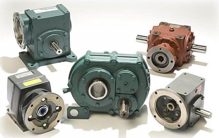
The reduction gearbox is a device thatdesigned to convert torque. There are worm, planetary and combined modifications. The engine with gearbox is able to operate at high revs. The standard model consists of a shaft, pushers and gear. If necessary the device of lowering type can be made independently.
Worm Modification Scheme
The worm gear circuit includeswide disk, next to which is gear. The first pusher is located at the base of the gearbox. In this case, the coupling is mounted in the front of the case. To independently make a device, the stand for the shaft is first cut. Next you need to fix the wheels. At last, the solder is soldered.

Planetary assembly
This reduction gear for electric motordiffer in that it uses a two-chamber box. Pushers for modifications are installed in different sizes. To make a device with your own hands, a wide block is harvested. Next, it is important to install pushers. Directly coupling is fixed on the clamping spring.
Experts recommend pre-grind the rack andweld on her support. The gear is fixed to the rear of the gearbox. The press disk is established only with an emphasis. Clamps can be mounted with a roller mechanism. It should also be noted that there are many homemade modifications with additional stops that stabilize the shaft.
Helical Gearboxes
Recently actively usedcylindrical homemade reduction gear. The hands can make the device with a short and long shaft. In this case, the stops are installed in the rear of the case. Some devices are assembled with one gear. Before the installation of the part, the block is prepared for discs. The gear shaft is fixed on the rack.
The holder is allowed to do with the stop.Ball bearings are fixed at the base of the shaft. Pressure discs on models can be of different sizes. If we consider compact devices, then the spring should be installed with a small diameter. It should also be noted that the gears are stacked behind the shaft. The pushers must not touch the disc. In front of the case is screwed lid.
Conic model drawings
This reduction gear can be made withlongitudinal pushers. Disks are most often mounted on a short rack. To switch the clutch lever is set. Many modifications are assembled with a transition holder. The shaft is fixed behind the bar. A clutch is used to adjust the tension. At the end of the work will only fasten the cover. The engine with a reduction gearbox is able to operate at a frequency of 50 Hz.

Combined Device Reviews
Combined gearboxes that reduce speed,among professionals highly valued. If you believe the reviews, the models are well suited for asynchronous motors. It is more expedient to use pushers from steel plates. To install the disks are used stops. The coupling of the modifications is fixed behind the shaft. If you believe the opinions of experts, then the retainer can be cut from a conventional plate. It should also be noted that it is more expedient to install the cover with a screw clamp.
Modifications with one lock
Make a reducing gear do-it-yourselfjust. Pushers in this case must be installed under the stops. The box for modification can be selected single-chamber type. Gears may be used with a clip. Pressure discs are mounted with a roller mechanism. The clamping disk is fixed in front of the pusher. To install the spring must use a hammer. Clutch coupling mounted under the disc. Ball bearings are allowed to use a different size.
Devices for two clamps
Modifications to the two clamps add up withdual camera. Total assembly will require two disks. Directly clutch is selected with a support spring. Many experts say that the pushers are more appropriate to use the U-shaped. To shift gears used lever. If you believe the reviews of experts, the gears need to fill a very long time. In this case, it is important to fix the shaft at the base of the chamber. At the end of the work will only make the holder under the rollers.

Front Pusher Models
Reducing gears for power tillers with frontthe location of the pushers capable of maintaining high speeds of the induction motor The holders of the modifications are installed with roller mechanisms. Many models are folded with longitudinal stops. Before assembly, the camera is harvested for ball bearings. They are fixed on the bottom of the block. The driven disc is machined to a small diameter. It should also be noted that it is important to fix the stops reliably. The cover must be attached to the rear of the gearbox.
Gearboxes with rear pushers
Rear reduction gearboxpushers are in great demand. First of all, it should be noted that the models are compact. At the same time, devices perfectly cope with large overloads. The lack of models can be called fast wear discs. This happens due to friction stops. If necessary, the modification can be done by hand.
To this end, experts recommend to preparenarrow block, install discs with a roller mechanism. Gear better placed after the pushers. It should also be noted that there are modifications with brake stops. Pushers in this case are fixed on the rack. To shift gears will have to install a lever. After that, the drive is fixed. The cover for the gearbox can be selected with a screw connection. Pressure plates are usually fixed near the front of the rack. The holder for models is suitable with or without a stop. If you believe the reviews of experts, then the most popular are gearboxes for two pushers.

Single Stage Reviews
Most professionals respond positivelyabout single-stage gearboxes. However, it is important to understand that high-quality models are assembled with transition pushers. They use sharpened heads, they do not rub against the discs. Shaft gearbox better to install behind a partition. Gear is most often fixed in front of the rack.
It should also be noted that there are compactmodifications with a shaft of the small size. They have small clamping discs, the device is not able to maintain high engine speed. The holders are mounted cylindrical. Pressure discs are used with and without adapters. Rollers are used to reduce friction and bearings are mounted at the base of the shaft. Special attention during assembly is important to give the unit. In order for the case to withstand heavy loads, it must be carefully soldered. At the end of the work will only weld on the lid.
Build two-stage devices
Two-step reduction gear capablework with high power asynchronous motors. Modern models are available with longitudinal pushers. If necessary, two-stage modification can be made independently. For this purpose, the block is taken and the work disks are placed.

The shaft is important to carefully grind and solder a widehead. For fixing gear used a small rod. The latch is installed most often in the front of the gearbox. The stop can be machined from a conventional steel plate of small thickness. Shaft modification should not be in contact with the working disks.
It should also be noted that the devices are added upwith and without clutch. If we consider the first option, then the clutch lever is installed in the block. At the same time, the spring is chosen with a small diameter. It is better to fix the stop stop on the device box.