In shops, you can often find switches, inwhich already built in the backlight. However, it's unlikely that someone will want to change the installed switch. But to look in the dark, the key to the touch is also not always convenient.
Practicality of switches with illumination
Switch with illumination, connection diagramwhich is almost the same as that of conventional switches, has become very popular. Anyone who is tired of looking for a switch in the dark at night can make small changes to this device, even if it does not have special knowledge in the electrician.
In any switch you can insert an LED,using rather simple schemes. Among themselves, the available schemes differ in their characteristics, and not only in their bundling. For example, the switch may not want to work because the LED lamp is installed in the luminaire. If the lamps are energy-saving, they can glow in the dark or flicker, which is also not the right result.
Circuit diagrams of circuit breakers
There are many acceptable schemes, each of which has its pros and cons. Understand the existing schemes for connecting LED backlighting to the switch is not difficult.
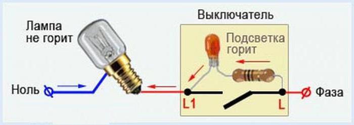
For example, a switch with a backlight, the circuitry of which is shown below.

When the switch is in the"Off", the current passes through the resistance (R1-any, in the range from 100 to 150 kOhm). After the resistance, it passes through VD2 (the LED that glows). In order to protect the LED from the voltage, we put the diode VD1. The resistor with a current of 3 mA shines particularly well with this connection scheme. If it turns out that the LED glows a little, then the resistance value should be reduced. The LED and diode in this circuit will suit any. You can also calculate the necessary resistor parameters yourself. It is enough just to recall the classical law of current strength.
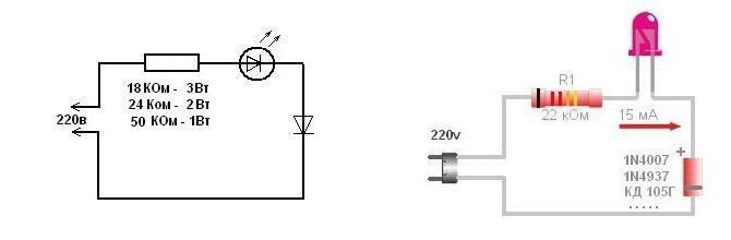
Let's consider one more switch with illumination, the circuit of which connection is extremely simple, but with a small defect. The fact is that it consumes about 1 kilowatt per month.
The ends directed downward are connected to the terminals.If there is no soldering iron in the house, or for some reason there is no desire to tinker with it, then this scheme fits perfectly. It is made on twists. Although, for reasons of safety and longevity of the device, it is better to connect the connection points, and the resistor must be properly insulated.

Diagram of LED illumination of a switch with a capacitor
To increase the level of luminescence an order of magnitude,use condenser. A resistor current, on the contrary, reduce to 90-100 Ohm. You can use a switch with a backlight, the connection circuit of which differs from the previous one in that a capacitor is used instead of a resistor. And the resistor (R1) plays the role of a limiter of the charging current.
However, the illumination collected according to this scheme differs in large dimensions, but it differs by extremely low power consumption - about 0.05 watts per month.
Connection of the pass-through switch
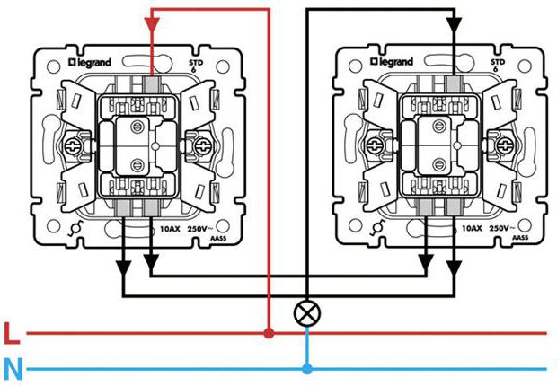
If we consider the Legrand switch withbacklighting, the connection diagram of which is higher, it should be noted that it is distinguished by the safety of using this product, which is made of materials that significantly increase the service life. And it's not necessary to talk about the simplicity of connecting the switches of this company, so everything is thought out and easily implemented.
When manufacturing switches,polycarbonate and galvanized steel. Screws, grips and caliper - all this is made of this metal. Polycarbonate made keys, mechanisms, body and frame. And this is a guarantee that for a long time the "Legendar" switch with backlighting, the connection scheme of which is extremely simple, will not crack and will not break from the sunlight.
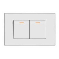
Installation of a two-button switch
Two-key pass-through switches LegrandThe presence of a pair of contacts independent of each other. When pressing the keys, they switch the upper lines to the lower ones, and the upper contacts are made with no final output. And the bottom contacts are connected to the second, same pass-through switch.
Knowing how the left and right groups of contacts are arranged, it is easy to understand how to connect a pass-through switch.
Connection of a pair of feedthrough switchesjust. The phase that emerges from the electrical panel of the apartment or house is fed to the contact of the second switch, while within the whole group the contacts are connected by a bridge with each other. And those contacts, which are in the left group, supply current to independent lighting devices. It is important to consider one rule. These two contacts must in no case be connected to each other. Then all the crossed four contacts must be linked together as a pair.

Legrand Switches
"Legrand", perhaps the most common brand among electrical appliances, and therefore most prefer to use their products, or close to them, but also well-known companies.
Among the products related to the electricalfittings, it is necessary to allocate and sockets suitable for television and telephone networks - low-current, and all of them, except for the excellent design, are of high quality, from where they gained wide popularity not only in our country, but all over the world.
Principle of operation of pass-through switches
Externally, a conventional switch is almost notdiffers from the gateway and visually distinguish them without revealing the structure, it is impossible. The difference lies in the internal arrangement. A conventional switch opens or closes a circuit carrying an electric current, and a gateway, connecting one line, while disconnecting the other. That is, in other words, when the loop switch is operating, no matter which key pair is pressed, the switch is ready for operation. Pressed the left one on the switch - the lamp went out. Pressed the second on it, or the key on the second switch - the light is on again. This is undoubtedly very convenient.
In other words, the usual single-keycircuit breaker, both contacts are working, and the pass-through has as many as three. Because the second contact, which acts as an output contact, is connected to the second switch, pair. And when connecting two-key pass-through switches, the number of contacts increases to six.
If you carefully consider the connection scheme,given below, you can easily cope with the installation of any pass-through switches and install all the necessary devices in order for the circuit to function properly. The main thing is to observe the safety precautions, do not work when the voltage is on in the network and make sure that a workable scheme is used.
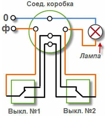
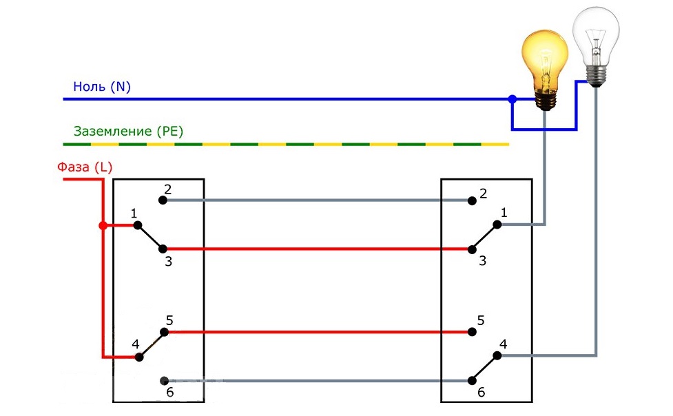
Illuminated continuous switch connections
Consider, perhaps, the most undemandinga circuit with which you can connect such switches. Zero in the diagram is marked in blue. He, hitting in the junction box, then goes to the light bulb. The orange wire is the phase. It passes from the same box to the input of the first of the switches. Then, at the outputs, the black wires must be connected to the input terminals of the second switch. And then, by just one wire go to the lamp.
Double switch with backlight, circuitthe connection of which is identical to those considered, is used as a device for controlling lighting sources that are spaced from each other and can be located at a considerable distance. But they need to be managed from a particular place, and sometimes from two or three.
The comfort effect is especially noticeable whena illuminated double-button switch is used, the wiring diagram of which is included in the kit, on the stairs, in large rooms, when you don't want to get up, for example, from a bed, to turn off the light in the bedroom. If the switch is located at the door - it is inconvenient at bedtime. Therefore, it is more logical to use a loop switch. One is installed as usual at the door in the room, and the second near the bed so that you can turn off the light without getting up.
Often use automatic adjustmentoff and on the light. For this purpose, detectors are connected to the light bulbs that react to movement or sound. Or on the lighting - when it becomes dark, the light turns on independently and vice versa.
Thus, if single-key is useda backlit switch, the connection scheme of which has already been considered, as well as pass-through switches with different numbers of keys, any results in the implementation of design ideas and projects are easily achieved. And the ease of installation determines the possibility of independent work, without resorting to the services of expensive professionals.